Progarchives.com has always (since 2002) relied on banners ads to cover web hosting fees and all.
Please consider supporting us by giving monthly PayPal donations and help keep PA fast-loading and ad-free forever.
/PAlogo_v2.gif "Progarchives.com Homepage") |
|
Post Reply 
|
Page <12 |
| Author | |||
Catcher10 
Forum Senior Member 

VIP Member Joined: December 23 2009 Location: Emerald City Status: Offline Points: 17498 |
 Posted: October 27 2014 at 10:58 Posted: October 27 2014 at 10:58 |
||
|
sweet
|
|||
  
|
|||
 |
|||
|
Meltdowner
Special Collaborator 

Honorary Collaborator Joined: June 25 2013 Location: Portugal Status: Offline Points: 10215 |
Posted: October 27 2014 at 14:18 |
||
|
Great work Dean! By the way, what's that thing on the top left side for?
|
|||
|
|||
|
Argonaught
Forum Senior Member

Joined: June 04 2012 Location: Virginia Status: Offline Points: 1413 |
Posted: October 27 2014 at 16:14 |
||
If you mean on the top left of the table itself (not the separate unit to the left of it), this must be a slat that covers the motor and pulley assembly .. right?
|
|||
|
|||
|
Meltdowner
Special Collaborator
Honorary Collaborator Joined: June 25 2013 Location: Portugal Status: Offline Points: 10215 |
Posted: October 27 2014 at 16:21 |
||
|
^ No, I meant the unit to the left. I didn't noticed it was separated, and now that I think of it, how do those two buttons work?
|
|||
|
|||
|
Argonaught
Forum Senior Member
Joined: June 04 2012 Location: Virginia Status: Offline Points: 1413 |
Posted: October 27 2014 at 16:53 |
||
|
^ That would be his power supply (I think I am seeing a heat sink on it?), and speed control circuitry. He wants it separate so as to decouple any 60 Hz vibration and maybe inductive currents from the table itself.
|
|||
|
|||
|
Dean
Special Collaborator

Retired Admin and Amateur Layabout Joined: May 13 2007 Location: Europe Status: Offline Points: 37575 |
Posted: October 28 2014 at 06:04 |
||
Correct, but here in "the rest of the world" we used 50Hz. Unfortunately the motor is an 110v AC motor so that source of noise is still present in the turntable plinth. I could replace that with a DC motor but I want to retain all of the Connoisseur components, including the motor. I've kept the power-supply and speed control circuit separate more for aesthetics than any practical consideration - it also means that at some later date I can replace that box with a different design if I want to.
The two buttons are "Stop/Start" and "Speed Select". Power to the box is "always on" so that the speed control circuit and motor drive amplifier is always at working temperature, which improves stability. Therefore the "Start/Stop" simply gates-off the drive signal to the motor drive amplifier, and the "Speed Select" switches the clock circuit divider to divide the quatrz controlled master clock by the appropriate value. I originally intended them to be touch switches then changed my mind and redesigned them to be lever style push-buttons like a piano key. However, I didn't want them to latch mechanically so used a non-latching sub-miniature micro-switch and designed the latching function part in electronics. This is very similar to how the soft-touch "push-on/push-off" foot-switch on Ibanez and Danoelectric effects peddles work. For those who understand digital electronics, the circuit looks like this: 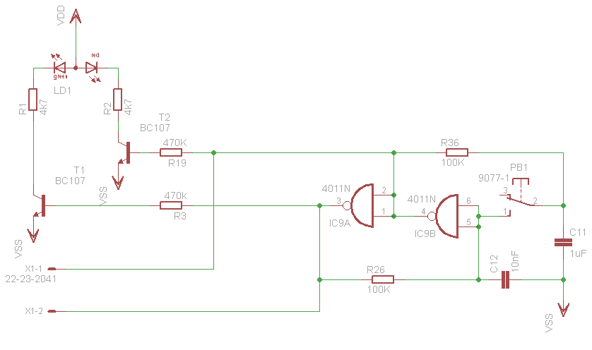 ..which is a simple toggle-latch that lights either a green (ON) or red (OFF) LED - the two output lines (X1-1 and X1-2) go to the Speed Control circuit. And mechanically, it looks something like this: 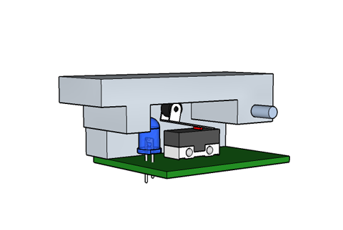 (the LED is bi-colour) A similar piano key circuit is used to raise and lower the tonearm. In the photograph the arm-lift is not yet fitted as I'm still working on the electro-mechanical part of the design. |
|||
|
What?
|
|||
|
|||
|
Argonaught
Forum Senior Member
Joined: June 04 2012 Location: Virginia Status: Offline Points: 1413 |
Posted: October 28 2014 at 07:00 |
||
Indeed so; and neither do you all use split-phase home power supply :)
Clever stuff. Is this how these things work in mass-produced equipment as well, or it's Mr. Dean's ingenuity shining through?
I do know one or two things about semiconductors, but from an different angle: what to make them from. The 4011 are metal oxide NAND gates that remain latched in a certain position until the next signal? Meltdowner is studying electronics, so he should understand more. [/QUOTE]
|
|||
|
|||
|
Meltdowner
Special Collaborator
Honorary Collaborator Joined: June 25 2013 Location: Portugal Status: Offline Points: 10215 |
Posted: October 28 2014 at 08:04 |
||
|
^ I studied Computer Engineering, which had a basic Electronics class
and I was really bad at it, probably because one professor didn't say
anything the whole class and the other taught like we were specialized
in Electronics. So I ignored those classes and learned everything from
scratch by myself and after three months of intensive studying, I
finished with 55% and it was the second best grade
 Anyway, if I understand correctly, if the switch PB-1 is at 3 the red LED is on and if it's at 1, the green LED is on and somehow those NAND gates will indicate the speed control circuit to start and at what speed. Can you correct this Dean? 
|
|||
|
|||
|
Argonaught
Forum Senior Member
Joined: June 04 2012 Location: Virginia Status: Offline Points: 1413 |
Posted: October 28 2014 at 09:38 |
||
|
^ speaking out of turn (again!), I believe that this piece of circuitry is an electronic toggle switch only. To control the AC motor rpm, he needs to feed it a certain frequency. So, there will have to be another circuit that would rectify and smoothen his mains AC into a more or less DC and then get something to flip-flop its polarity continuously at the desired frequency. I won't say any more, because I am already picturing myself a bridge, followed by an LC filter, followed by an oscillator, tuned to the frequency he wants, but Dean will likely do it in a less old-school way.
|
|||
|
|||
|
Dean
Special Collaborator
Retired Admin and Amateur Layabout Joined: May 13 2007 Location: Europe Status: Offline Points: 37575 |
Posted: October 28 2014 at 10:47 |
||
It has been a long established practice in audio circles to keep power amps permanently powered as they can take up to 20 minutes to settle down to their working temperature and bias levels. You wouldn't do a comparative listening test on cold equipment for example. Certainly when we design, build and test them any adjustments are made after their ambient temperature has stabilised so it would be logical to allow a similar time to elapse before using it. Since the drive circuit for the motor in my tt design is simply an audio power amplifier extending that practice to this turntable also seems logical. [My NAD 3020A has been switched on since I first bought it back in 1982 and only gets switched off when I move house or there is a power cut. It is a testament to the NAD design engineers that it has not given me any trouble whatsoever in 32 years of (literally) continuous use. Personally I don't know if it makes any difference to the listening pleasure but not power-cycling an amp puts less strain on the components.] Of course most remote-controlled equipment has a "standby mode" that switches off some of the circuitry but keeps the IR link powered so you can switch it back on. |
|||
|
What?
|
|||
|
|||
|
Catcher10
Forum Senior Member
VIP Member Joined: December 23 2009 Location: Emerald City Status: Offline Points: 17498 |
Posted: October 28 2014 at 11:29 |
||
|
There are tons of online debates about "power on or power off".....What I think people miss is the point that Dean makes is that it is not about "I leave my amp powered on 24/7 because it sounds better.....". I also have a NAD integrated amp and will power it ON on Friday and not turn it off till Sunday late evening. It has a "standby" mode so I am not "powering it off" when I hit the power button.
But for 3 days it is on 24/7......During winter months when I listen a lot, I leave it on for months. I do turn off my DAC since it has a tube, a tube only has so many hours. Then you have the people that argue you have to turn it off.....well my refrigerator has been running ON for 15yrs in my current house and I can count on one hand how many hours it has been off in those 15yrs, and it still keeps my food cold and safe to eat today.... Habit just keeps me from leaving my gear on 24/7, I hear my dad in my head screaming at me to "turn it off...your wasting electricity!!"
|
|||
|
|
|||
|
|||
|
Dean
Special Collaborator
Retired Admin and Amateur Layabout Joined: May 13 2007 Location: Europe Status: Offline Points: 37575 |
Posted: October 28 2014 at 12:04 |
||
|
Hmm, this is going to be a test of my powers of explanation

Oh man, your Lecturers/Teachers need their arses well and truly kicking, that's abysmal. Their role is to teach everyone in the class. Admittedly linear/analog electronics is a bit complicated even for the basic stuff, but logic/digital electronics isn't exactly difficult to teach.
The switch is a push button, when pressed it switches to 1 but when release if springs back to 3. Without the logic gates I would have to permanently hold my finger on the switch to select 45rpm. The two NAND gates remember that the push-button has been pressed and hold the circuit in the required state until I press it again. In that circuit schematic you'll notice that the inputs of the NAND gates are wired together, therefore I am using them as Inverters or NOT gates ... a "1" on the input will set the output to "0" and a "0" on the input will set the output to "1". The circuit works like this:
One way to look at this is C11 and C12 are the circuits "memory" - C11 remembers the "1" or "0" on IC9b's input and C12 remembers the Inverted level on IC9bs output. Therefore C12 will always be in the opposite state to C11: when C11 is "1", C12 will be "0" and when C11 is "0", C12 will be "1". The push-button switch is used to overwrite C11 with the voltage remembered by C12.  I hope that isn't too confusing. I hope that isn't too confusing.
Yes, the circuit above is only part of the full circuit and is only the latching circuit for the switch. I've drawn it in a non-standard way to make the component layout easier in the schematic, essentially it is a cross-coupled bistable "flip-flop" that you'd normally seen drawn like this:  In that configuration I would need two push-buttons, one to "SET" the latch and one to "RESET" the latch. As explained above, the capacitors in my circuit allow me to do that with one push-button (push-to-set, then push-to-reset). I'll not show the complete circuit diagram for the speed controller since that is currently my unprotected IP and I'm not in the mood to share  However, I will try and explain the principle: However, I will try and explain the principle:The Q and Q/ outputs are used to set the divide ratio of a CD4059 (programmable divide-by-n counter) to either 216 or 160. The clock for this counter is generated from an 11.0592MHz quartz crystal wired to a CD4060 14-stage ripple counter that is preset to divide that crystal frequency by 128. Together these two counters will produce a clock of either 400Hz or 540Hz depending on the state of the speed-selector latch. This is then divided by 8 to produce the 50Hz (or 67.5Hz) needed by the motor. The reason why I do this in three stages is so I can insert a phase-locked-loop (PLL) into the circuit that monitors the platter speed and adjusts the clock frequency accordingly. Rather than use a filter to produce a sine-wave I am using a DAC to create a pseudo sinewave from a binary sequence. Precisely how I do this will remain a secret for now, because if I ever find myself out of work with a hefty redundancy cheque, I would like the opportunity to make this control circuit commercially and sell it to owners of Linn, MH, Rega and Pro-ject turntables.  Edited by Dean - October 28 2014 at 12:07 |
|||
|
What?
|
|||
|
|||
|
Padraic
Special Collaborator

Honorary Collaborator Joined: February 16 2006 Location: Pennsylvania Status: Offline Points: 31165 |
Posted: October 28 2014 at 12:25 |
||
|
Cool project Dean.
|
|||
|
|||
|
Meltdowner
Special Collaborator
Honorary Collaborator Joined: June 25 2013 Location: Portugal Status: Offline Points: 10215 |
Posted: October 28 2014 at 12:59 |
||
Not confusing at all, don't ever doubt your powers of explanation  I didn't know what the capacitor was (it was not on that class' program ), but I understood how it worked when you explained.I also didn't noticed about that NOT gate with NAND's, although I immediately remembered about the NAND gate being a universal gate. Thanks for the lecture  |
|||
|
|||
|
Argonaught
Forum Senior Member
Joined: June 04 2012 Location: Virginia Status: Offline Points: 1413 |
Posted: October 28 2014 at 17:39 |
||
|
^ What an illuminating discussion!
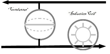
Speaking of the Art of Explanation ... I remember reading a late 19th century book on electricity. People had been already using electricity in earnest, but had no idea what it was. Engineers used hydraulic analogies to describe the rules of behavior of electric current: voltage was pressure, current was the flow of water, resistance was a narrowing section of the pipe, the power source was a water pump etc. To help visualize how a capacitor (aka condenser) works, they depicted it as a bladder tank; induction coils were like water wheels J Ive reproduced the pic as I remembered it. As you can see, the capacitor fills up with water on one side until its pressure is canceled by the counter-pressure from the stretching rubber diaphragm in the middle. Once you remove the inlet pressure, the diaphragm will contract and discharge the water back into the pipe.
It occurred to me that you could even explain the diode (= check valve) and the transistor (= a garden hose faucet with spring-loaded handle) in these hydraulic terms! |
|||
|
|||
|
Meltdowner
Special Collaborator
Honorary Collaborator Joined: June 25 2013 Location: Portugal Status: Offline Points: 10215 |
Posted: October 28 2014 at 18:31 |
||
|
^ Great analogies, really easy to undestand. I use all kinds of analogies to learn things, most of the stupid that only I can understand, but it works
 |
|||
|
|||
|
Catcher10
Forum Senior Member
VIP Member Joined: December 23 2009 Location: Emerald City Status: Offline Points: 17498 |
Posted: October 29 2014 at 10:30 |
||
very cool!
|
|||
|
|
|||
|
|||
|
Post Reply
|
Page <12 |
| Forum Jump | Forum Permissions You cannot post new topics in this forum You cannot reply to topics in this forum You cannot delete your posts in this forum You cannot edit your posts in this forum You cannot create polls in this forum You cannot vote in polls in this forum |


 Sugden Turntable...")


 Vintage (ish) Sugden Turntable...
 Topic Options
 Meltdowner wrote: